|
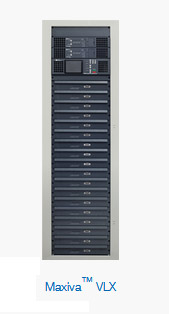
The Maxiva™ VLX VHF liquid-cooled transmitter (formerly Platinum™ VLX) delivers the newest and most advanced VHF transmission platform with exceptional power efficiency, superior RF performance, and a modular user-friendly design. These capabilities along with the Maxiva VLX’s flexible configurations and superior power density provide the critical features upon which broadcasters can build their network.
The Maxiva VLX incorporates the PowerSmart® solid-state architecture with 50 Volt LDMOS amplifier devices and the Maxiva M2X™ exciter technology with RTAC™ to provide today’s broadcaster with leading power efficiency and unmatched signal performance. The VLX power amplifiers have a record of proven performance and reliability with Harris Broadcast transmitters and are in use around the world. This powerful blend of technologies provides best-in-class performance with respect to power efficiency, transmitter size and user features. The modular design allows for simpler installation, easier maintenance and reduced total cost of ownership over the life of the transmitters. The VLX is available over a wide range of output power configurations that are suitable for broadcast applications where liquid cooling and space considerations are a premium.
The Maxiva VLX transmitter is capable of multiple modulation schemes for band III VHF analog or digital TV and digital radio operation — including ATSC, ATSC MDTV, DVB-T/H, DVB-T2, ISDB-Tb, DAB/DMB and future digital standards. Upgrading from analog to digital or to newer digital standards is readily accomplished to further extend the capability and life of the transmitter.
FEATURES
- PowerSmart technology, for best-in-class power efficiency and lowest operating costs
- Rugged, reliable design and construction
- Digital power levels up to 33.6 kW ATSC, 28.8 kW DAB and 19.2 kW
- DVB-T/DVB-T2/ISDB-Tb
- Analog power levels up to 48 kW
- Incorporates field-proven Maxiva M2X exciter technology, allowing easy migration from analog to digital or between different standards
- All-digital linear and nonlinear pre-correction, including exclusive Real-Time Adaptive Correction (RTAC™)
- Fully broadband PA ruggedized modules — 168 to 242 MHz
- 1:1 PA pallet to power supply redundancy
- Hot-pluggable linear RF amplifier modules
- Transmitter monitoring and in-depth diagnostics via easy-to-use, front-panel controls
SPECIFICATIONS
Specifications and designs are subject to change without notice.
| General |
| Frequency Range |
168 to 242 MHz, in 1 Hz steps |
| Transmission Standards |
ATSC, DVB-T, DVB-T2, ISDB-Tb, Analog, DAB |
| Channel Bandwidth |
1.5, 6, 7 or 8 MHz (system dependent) |
| Rated Power Output |
See chart below |
| Output Power Reduction Range |
0 to -10 dB |
| RF Load Impedance |
50 ohms |
| VSWR |
Protected against open or short circuit, all phase angles. Capable of operation into infinite VSWR with user-adjustable fold back threshold. Factory pre-set to 4% of nominal nameplate power (VSWR = 1.5:1) |
| RF Output Connector |
N-female, 1-5/8 or 3-1/8 in. EIA (dependent upon power level, DIN 7-16 optional for lower power levels) |
| |
| AC Mains |
| AC Line Voltage |
3 phase: 380 to 415 V, or 208 to 240 V, 50/60 Hz - specify when ordering |
| AC Line Variation |
±15%, between 208 to 230 V, or 380 to 400 V |
| Power Factor |
>0.97 (0.98 typical) |
| |
| Environmental |
| Altitude |
Up to 13,123 ft (4,000 m) elevation above mean sea level |
| Ambient Temperature |
32° to 113° F (0° to 45° C) at sea level (upper limit derated 3.6° F (2° C) per 984 ft (300 m) elevation AMSL) |
| Humidity |
95%, non-condensing |
| Cooling Method |
Liquid-cooled, using 50/50 mix of ethylene or propylene glycol and water |
| Acoustic Noise |
<65 dBA (measured 1 m (3.3 ft) in front of cabinet) |
| Frequency Stability |
Without precision frequency control/GPS: ±150 Hz/month (6.2 x 10⁻⁷ppm) |
| |
| External Inputs |
| GPS Input |
SMA female, 50 ohms, (+5 V DC @ 100 mA max output for active antenna) |
| 1 PPS Input |
BNC female, user selectable 50 ohms or high impedance termination |
| 10 MHz Reference Frequency Input |
BNC female, 50 ohms |
| |
| Monitoring Outputs |
| RF Monitor (exciter) |
SMA female |
| 1 PPS |
BNC female |
| 10 MHz |
BNC female |
| |
| DVB-T/DVB-T2 / ISDB-Tb Specification |
| Power Output (average) |
800 W to 6.4 kW models available, measured before mask filter (see chart below) |
| Systems |
DVB-T, standard EN 300744
DVB-T2, standard EN 302 755
ISDB-Tb, Brazil ANATEL standard |
| ASI/T2MI Inputs |
2 inputs BNC female; 75 ohms according to EN 50083-9 (2 main/2 hierarchical) |
| Crest Factor |
13 dB maximum |
| Shoulder Level |
<-37 dB (before mask filter) |
| END |
<0.5 dB |
| MER |
>33 dB (typical 35 dB) |
| Harmonics (before filter) |
<-40 dB |
| Central Carrier Suppression |
>75 dB |
| DVB-T2 Modes |
Supports multiple PLP’s, MISO, extended bandwidth mode, PAPR reduction |
| |
| DAB/DMB Specification |
| Power Output (average) |
1.2 kW to 9.6 kW models available, measured before mask filter (see chart below) |
| Systems |
DAB/DMB (OFDM) ETSI EN 300 401 & ETSI TR101 496-1 |
| Power Stability |
≤ ±0.25 dB |
| Harmonic/Spurious Output |
Complies with EN 302077-2 when used in conjunction with proper band pass filter |
| Shoulder Before Filter |
35 dB minimum, >36 to 40 dB typical |
| MER |
>25 dB |
| Signal Inputs |
ETI Input: BNC-female, user selectable 75 ohms or high impedance termination. 2x ETI (NI, G703) or 2x ETI (NA, G704), seamless input signal switch-over automatic optional
EDI Input: 10/100 Base T RJ45, per ETSI TS 102 693 V1.1.2, 1 channel, UDP/DCP or TCP/DCP protocol |
| Monitoring Outputs |
ETI Monitor
2.048 MHz
Sync ETI
Sync OFDM |
| |
| ATSC Specification |
| Power Output (average) |
1.4 kW to 11.2 kW models available, measured before mask filter (see chart below) |
| System |
ATSC A-53, 8-VSB DTV standard |
| Data Input |
19.39 Mb/s, configurable as SMPTE-310M or ASI (user selectable) |
| Impedance |
75 ohms, unbalanced |
| Input Connector |
2 inputs, BNC female |
| Signal to Noise (EVM) |
>27 dB (EVM < 4%), Typical >32 dB (EVM <2.5 %) |
| Phase Noise |
<104 dBc/Hz @ 20 kHz offset (ATSC A/64) |
| Harmonic Radiation and Spurious |
Meets mask requirements specified in FCC 5th and 6th report and order |
| Sideband Performance |
Compliant with FCC radiation mask, when measured at the output of Harris Broadcast-supplied output filter |
| |
| Analog |
| Power Output (vision peak of sync) |
2.0 kW to 16 kW models available, measured before IMD filter (see chart below). 10% Sound |
| Analog Television Systems |
CCIR G, I, K, K1, M, N |
| Color Systems |
PAL, NTSC, SECAM |
| Sound Systems |
Monaural, BTSC, IRT, NICAM G |
| |
| Analog Video Performance |
| Video Input |
0.7 to 1.4 V, 75 ohms, 32 dB return loss |
| Variation of Output Power2 |
±2% |
| Vision Sideband Response3 |
PAL system G shown (other systems available)
-1.25 MHz and below -20 dB or less
-4.43 MHz -30 dB or less
-0.75 to -1.25 MHz 0.5 dB or less
-0.5 to 4.5 MHz 0.5 to -0.5 dB
5.0 MHz 0.5 to -2.5 dB
5.75 MHz and above -35 dB or less |
| Differential Gain5 |
3% |
| Differential Phase5 |
3° |
| Low Frequency Linearity6 |
10% |
| Incidental Carrier Phase Modulation5 |
±2° |
| Signal to Noise Ratio |
>60 dB (weighted) |
| K Factor |
2% or less with 2T sin2 pulse |
| 20T Equivalent Gain and Delay |
3% total baseline distortion |
| Spurious and Harmonic Radiation |
-60 dB, or better |
| In-Channel Intermodulation Distortion |
-58 dB (-60 dB typical) |
| |
| Analog Sound Performance |
| Modulation Capability |
±120 kHz peak deviation |
| Monaural Input |
Adjustable 0 to 12 dBm, 600 ohms, balanced, >30 dB return loss |
| Pre-emphasis |
Selectable 75 or 50 µS |
| Frequency Response |
±0.5 dB, 40 Hz to 15 kHz |
| Harmonic Distortion |
0.5%, 30 Hz to 15 kHz |
| FM Noise |
60 dB RMS with de-emphasis |
| AM Noise |
50 dB RMS from 30 Hz to 15 kHz |
| Synchronous AM Noise |
40 dB RMS at 400 Hz with ±25 kHz deviation |
| IRT Sound |
Available |
| NICAM Sound |
Available |
| |
| Remote Control |
| Parallel Remote |
12 conductor terminal block (mini Wago) |
| Ethernet/SNMP |
RJ-45, twisted pair |
| |
| Compliance |
RoHS 2002/95/EC
R&TTE 1999/5/EC
Safety: EN 60215
EMC: EN 301-489-1
FCC Part 73
Manufacturing: ISO 9001: 2008 |
1 Variation of peak output power with a change in average picture level from black to white (0% to 100%).
2 Peak-to-peak variation of peak sync voltage during one field using field test signal per EIA-508.
3 Response specified for transmitter operating into a resistive load of 1.05:1 VSWR.
4 Measured using 20% peak-to-peak amplitude swept video modulation with pedestal set at 10%, 50% and 90% APL. All percentages relative to a blanking to white transition.
5 Measured using a 5-step staircase signal. Test signal #3, CCIR REC. #421-3.
VLX Power Levels
| Model Number |
Number of Cabinets |
Number of PA Modules |
RF Output Power (W)
Pre-Filter |
| VLX-2000AN |
1 |
2 |
2,000/200 |
| VLX-1200DA |
1,200 |
| VLX-1400AT |
1,400 |
| VLX-800DV/T2/IS |
800 |
| |
| VLX-4000AN |
1 |
4 |
4,000/400 |
| VLX-2400DA |
2,400 |
| VLX-2800AT |
2,800 |
| VLX-1600DV/T2/IS |
1,600 |
| |
| VLX-6000AN |
1 |
6 |
6,000/800 |
| VLX-3600DA |
3,600 |
| VLX-4200AT |
4,200 |
| VLX-2400DV/T2/IS |
2,400 |
| |
| VLX-8000AN |
1 |
8 |
8,000/800 |
| VLX-4800DA |
4,800 |
| VLX-5600AT |
5,600 |
| VLX-3200DV/T2/IS |
3,200 |
| |
| VLX-12000AN |
1 |
12 |
12,000/1,200 |
| VLX-7200DA |
7,200 |
| VLX-8400AT |
8,400 |
| VLX-4800DV/T2/IS |
4,800 |
| |
| VLX-16000AN |
1 |
16 |
16,000/1,600 |
| VLX-9600DA |
9,600 |
| VLX-11200AT |
11,200 |
| VLX-6400DV/T2/IS |
6,400 |
| |
| VLX-32000AN |
2 |
32 |
32,000/3,200 |
| VLX-19200DA |
19,200 |
| VLX-22400AT |
22,400 |
| VLX-12800DV/T2/IS |
12,800 |
| |
| VLX-48000AN |
3 |
48 |
48,000/4,800 |
| VLX-28800DA |
28,800 |
| VLX-33600AT |
33,600 |
| VLX-19200DV/T2/IS |
19,200 |
Modulations
AN - Analog
DA - DAB
AT - ATSC
DV - DVB-T
T2 - DVB-T2
|